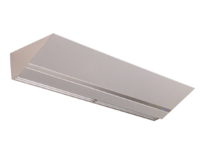
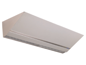
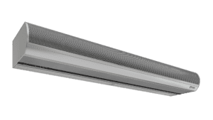
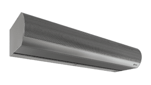
YES! Air curtains, a.k.a. air doors, properly selected, installed and operated really do work to create a barrier out of air across an opening. So much so, that ASHRAE Standard 90.1-2019 and the IECC building code allows air curtains as an alternative to vestibules. Read more here.
YES!
Energy Conservation & Comfort: Research shows that properly selected, installed and operated air curtains are +/- 80% effective at keeping warm air on one side and cold air on the other when the door is open.
Flying Insect Control: Research with the USDA shows that air curtains are effective at preventing flying insects from passing through the air stream formed across the opening.
Monday – Friday, 8:00 a.m. – 5:00 p.m. EST. Closed on major holidays.
To find a rep in a given area, give us a call at 800.245.4455, or e-mail us using the Contact Sales form.
Depends on where you are, call us at 800.245.4455.
We are happy to help with that, give us a ring at 800.245.4455. Or, if you prefer to do it on your own: Air Curtain Selector.
You can get quick answers to your shipping questions by calling 800.245.4455.
Berner Reps, log into http://extranet.berner.com/
When an order ships, a Shipping Notification e-mail is sent with the tracking number included. If you did not receive or cannot find, call 800.245.4455.
We are located an hour north of Pittsburgh, Pa., in the Shenango Industrial Park at:
111 Progress Avenue
New Castle, PA 16101
From, with no traffic:
Cleveland, Ohio: 1 hour and 43 minutes
Erie, Pennsylvania: 1 hour and 29 minutes
Pittsburgh, Pennsylvania: 51 minutes
All Berner air curtain models with the exception of Drive-Thru Units and the Air Entrance Systems, have a limited warranty of five years on unheated models and two years on heated models from the original date of shipment. Berner Air Entrance Systems have a two-year (2-year) limited warranty from the original date of shipment. Berner Drive-Thru Units have a one-year (1-year) limited warranty from the original date of shipment. Limited Warranty: Berner International warrants all new air curtains to be free of defects in workmanship and material. Claims will be honored for equipment that has been properly cared for, installed and operated. Warranty excludes any labor charges.
On most air curtains manufactured after 2010, the serial number is located on the bottom-right corner of the unit, just above the air discharge nozzle. On units older than 2010, look near the junction box.
We are happy to help with that, give us a ring at 800.245.4455. Or, use the Contact Us page.
We are happy to help with that, give us a ring at 800.245.4455. Or, use the Contact Us page.
Based on 100% indoor air, 4 CFM of outdoor air per 1,000 BTU/hour is required. The air curtain should be operated with the door open to entrain outside air with the air stream. This will provide approximately 25% to 30% of CFM of outside air included in the air stream to dilute products of combustion from the direct gas-fired heater.
The air curtain fans should not be operated with the door in a closed position. NFGC specifies a minimum of 4 CFM of outside air per 1,000 BTUs (provided from the heater) to dilute the products of combustion produced from the heaters.
A range of 1–5 pounds.
To provide even heat distribution. Air mixes more evenly with the burner flames, and the length is needed to control the flame.
FM (Factory Mutual), IRI (Industrial Risk Insurance) — most expensive, and ANSI (American National Standards Institute) — least expensive.
Spark ignition, power vented flues, aluminized steel heat exchanger and directional air intake louvers.
100 mbtu to 200 mbtu have a ½” NPT gas pipe connection and 230 mbtu to 400 mbtu have a ¾” NPT gas pipe connection. The maximum psig of gas heaters is ½ pound or 14″ of water column.
The minimum of one inch is to comply with the National Fuel Gas Code (NFGC). The minimum of one inch (1″) also provides a bypass, which prevents the gas-fired heater from creating a negative pressure on the air curtain fans.
To locate the bottom of the heater so that it is level with the bottom of the air curtain (heater dimension is taller than the air curtain).
The access panels are located on the bottom of the duct transition. They are constructed of aluminized steel, and they are not painted.
A flue should not be longer than 50 feet (50′) per AGA Code. A 90-degree elbow is equivalent to 15′ of flue pipe.
400 BTUs
Right here. Includes the Quick Start Guide and step-by-step directions for programming (operating) the Intelliswitch.
Instructions can also be found in the Installation Instructions for each air curtain model.
To unlock, press and hold the left and right arrows simultaneously for five seconds. See also “Why can’t I change my settings?” below.
Refer to the Installation Instructions for your air curtain. Installation Instructions are included with the air curtain, and can also be found here.
INTELLISWITCH FAQs:
WARNING: TO REDUCE THE RISK OF FIRE, ELECTRIC SHOCK OR INJURY TO PERSONS, OBSERVE THE FOLLOWING:
A.) Use this unit only in the manner intended by the manufacturer. If you have any questions, contact the manufacturer.
B.) Before servicing or cleaning unit, switch power off at service panel and lock the service disconnecting means to prevent power from being switched on accidentally. When the service disconnecting means cannot be locked, securely fasten a prominent warning device, such as a tag, to the service panel.
C.) Installation work and electrical wiring must be done by qualified person(s) in accordance with all applicable codes and standards, including fire-rated construction. (See page 4 V. ELECTRICAL CONNECTIONS – NEC Code ANSI/NFPA No. 70.)
D.) Sufficient air is needed for proper combustion and exhausting of gases through the flue (chimney) of fuel burning equipment to prevent back drafting. Follow the heating equipment manufacturer’s guideline and safety standards such as those published by the National Fire Protection Association (NFPA), and the American Society for Heating, Refrigeration and Air Conditioning Engineers (ASHRAE), and local code authorities.
E.) When cutting or drilling into a wall or ceiling, do not damage electrical wiring and other hidden utilities. Even though every Architectural Low Profile 8, Architectural Recessed 12, and Architectural Recessed 16 air curtain is individually tested at the factory before shipment, on occasion, improper functionality may be experienced.
The Intelliswitch may be locked. If the lock light is illuminated, the control is locked. To unlock, press and hold the left and right arrows simultaneously for five seconds. The lock mode can also be protected with a PASScode. If the PASScode option is on, an attempt to unlock the control will display PASS and then a 0000 prompt. A four-digit code (available in the installation instruction book Appendix) must then be entered to unlock the control. Use the up and down arrows to select a number and the left and right arrows to select the digit to edit. Press OK when done. Note: If the AutoLock setting is on, the control will re-lock if there is no activity after five minutes.
The thermostat(s) or speed sensor may need to be adjusted or replaced.
1.) Make sure that the thermostat probe and/or remote thermostat are in the “On” position and set above ambient (room) temperature.
2.) Check internal and external thermostat status in the Diagnostics Menu for a faulty thermostat. To do this, hold the right arrow for five seconds until DIAG appears, then arrow down to the ts setting. If it displays “1,” then the thermostat(s) is working (there is a call for heat).
3.) If no external thermostat is used, check to see if the internal probe is attached to the control board. Disconnect power to the unit, remove the display board and check that the beige sheathed cable is attached at both ends. If the thermostat(s) and settings are correct and you are still not getting heat, then check the fan speed. To do this, press the down arrow to reach the Mode/Fan speed setting. Use the right and left arrow to change the fan speed.
4.) Check to see if you can adjust the fan speed. If the speed sensor is bad, there will be no speed control and the Intelliswitch will not let the heat come on. If it is too difficult to determine a change in speed, the speed sensor can be checked by entering the DIAG menu and checking the first error code. If ER 10 displays, the speed sensor is recognized by the Intelliswitch. If the code ER 11 is displayed, the Intelliswitch does not recognize the sensor, and it may be faulty or need to be adjusted closer to the trigger bar. Turn off the power to the unit and remove the screen to check the distance between the sensor and the trigger located on the left side of the motor (use the bottom access cover for steam/hot water heated units). The sensor should be less than 1/16″ from the trigger face. Check distance at both ends of trigger. Adjust if necessary.
5.) If there is still no heat or speed control, you may need a new speed sensor. Consult the factory.
There may not be power to the control.
1.) Check to see if the main power is turned on to the unit. Your air curtain may have multiple disconnects, so make sure all are turned on.
2.) Verify that there is power to the board. NOTE: ONLY QUAILIFED PERSONS SHALL CHECK POWER IN THE UNIT WITH THE POWER ON. The power terminals are located directly behind the display. Remove two Phillips screws from the Intelliswitch display to expose the power terminals and check the line voltage at spade terminals L2 and 120, 208 or 240 (depending on the voltage supplied to the unit).
3.) Check the ribbon cable connections to the display board for a loose connector or improperly connected cable (see installation instructions for correct cable connection).
4.) If display still doesn’t light, unplug the speed sensor and thermostat probe (if a heated unit) from the control board. If the display lights, plug one component in at a time to see which one may be shorted. The faulty component will make the display go blank again.
5.) If there is line voltage power at the board terminals, the ribbon cable is correctly connected, and it is still not working, you may need a new circuit board. Consult the factory.
The Intelliswitch may be in the wrong mode or miswired.
1.) Check to see if the control is in the “On” mode. If it is, change the mode to another setting.
2.) The T-Stat Mode may be set to the “both” setting and the thermostat is calling for both fan and heat. Change the T-Stat Mode to “HEAT.”
3.) If there is a door switch and the unit is in a mode that is activated by it, there could be a short, mis-wiring or mix-up in components. Close the door and check the door switch status in the Diagnostics menu. Hold the right arrow for five seconds until DIAG appears, then arrow down to the ds setting. If it displays “1,” then the door switch signal is closed (there is a call for fan). If the door is closed, the signal should be “0” or open.
4.) There could be a short in the field connections to the door switch or the door switch leads could be mis-wired. To test, disconnect the door switch connection at the unit. Open the wiring tray on top of the unit and be cautious of high voltage connections. Disconnect the blue wires labeled 9 and 10 from the field wiring to the door switch or make sure they are not tied together. There is no danger of getting shocked because the signal is 5 volt dc. Be sure not to touch the blue wires to anything metal (or grounded). The unit should shut off when it is in any mode that is activated by the door switch.
5.) If the air curtain is heated, make sure that the thermostat isn’t wired to the door switch leads. Door switch leads are blue and labeled 9 and 10.
The Intelliswitch may be in the wrong mode, be mis-wired or have a faulty door switch.
1.) Test the wiring and controller function at the same time first. Locate the door switch and open its wiring compartment by removing the two screws holding on the back cover. There should be two wires connected to screws inside the switch. There is no danger of getting shocked because the signal is 5 volt dc. Be sure not to touch the wires to anything metal (or grounded). Either disconnect both wires from the screws (noting which screws the wires are under) and touch them together (with air curtain in “Auto” mode), or make a short jumper wire and touch the jumper to both screws at the same time to see if the air curtain comes on. If it does, the controller and wiring work.
2.) If the wiring and unit pass the function test, the problem could be either misalignment or a faulty door switch. For a magnetic reed switch, check for magnet alignment. For a plunger/roller type switch, check contact engagement with door.
3.) If you have access to an electrical test meter, the door switch contacts can be tested for continuity when the door switch wires are disconnected from the unit.
The Intelliswitch may need to be adjusted, have been mis-wired or have a faulty thermostat.
1.) Heat is activated by one of two thermostat connections. To test the internal thermostat, set the external thermostat to OFF. The settings of the unit-mounted thermostat probe are accessed through the display. Press the down arrow until the Temp Set indicator lights up; check if the temperature setting and unit of measure are correct. Test to see if it shuts off by setting the thermostat temperature to OFF or lower than the room temperature.
2.) If an external thermostat is connected to the unit, there could be a short in the field connections or the thermostat leads may be mis-wired. To test the external thermostat, set the internal thermostat to OFF. Disconnect the external thermostat connections at the unit. Open the wiring tray on top of the unit and be cautious of high voltage connections. Disconnect the orange wires labeled 6 and 7 from the field wiring to the thermostat or make sure they are not tied together. There is no danger of getting shocked because the signal is 5 volt dc. Be sure not to touch the orange wires to anything metal (or grounded). The heat should shut off when the wires are separated. For more complex troubleshooting of either thermal cutouts or heater contactors, please consult a qualified electrician or the factory.
If a program is active (a dot is illuminated by one of the clock digits), changes can be made to any settings on the User Menu. These changes, however, will only remain in effect until the program changes to the next time zone. To make changes permanent, settings must be changed in the program from the Program Menu. Access the Program Menu by holding down the left arrow for five seconds until “PRO” is displayed. Arrow down to select programming and arrow left to select the program to edit. Use the down arrow to step through the options and make changes as desired. Continue to press the down arrow until “Stor” is displayed. Press OK or down to keep or store the changes.
Changes to programs cannot be undone. The programs can, however, be reset to the factory default settings. This must be done on the Factory Menu. Access to the Factory Menu is attained through the Diagnostics Menu. Press and hold the right arrow for five seconds until “DIAG” is displayed. From the “DIAG” display, press and hold the up and down arrows simultaneously for 10 seconds until “FACT” is displayed. Use the down arrow to select “DEFn” on the display, then use the right arrow to select “DEFP.” Press OK to reset. The control display will go blank and then blink as confirmation.
Check the AM/PM setting on the Start and Stop times or the clock (considering the AM indicator light when setting values). Note: Set the start time and stop time to the exact time for the unit to be active full time. Check to see if a program is active that may have different start/stop times than those expected.
Try shutting off the power to the air curtain because the sensors are behind the high voltage connections:
1. Unplug the proximity sensor (gray wire with a white three-prong plug on the end) and the temp sensor if it’s a heated unit (the temp sensor is a brown wire with the same kind of three-prong plug on it). Carefully note the placement of each sensor. They are behind each other on the control board. The correct placement is printed on the control board as “proximity” and “temp.”
2. Turn the unit power on to see if the display comes back on. The display will come back if either of the sensors is shorted. Order a replacement sensor if display returns with sensor(s) unplugged.
3. If there is both a proximity sensor and a temp sensor, use the procedure above (turning the air curtain power off before plugging a sensor back into the board and then restoring power) and plug them back in one at a time to see which sensor is at fault.
The Intelliswitch can be controlled by a Building Management System (BMS) but currently does not have the ability to communicate with them. Dry contacts on the BMS may be used to control the unit activation through the door switch connections (blue wires 9 and 10) and the heat activation through the remote thermostat connections (orange wires 6 and 7). Consult the factory.
The air curtain ships with a paper copy inside the junction box or control panel of the air curtain. There is also a copy adhered to the inside panel of the air curtain.
Wiring instructions are placed inside the junction box or control panel of each air curtain shipped. There is also a copy adhered to the inside panel of the air curtain. If you cannot find it, call Berner at 800.245.4455. You will need the serial number of the air curtain.
If switches were ordered, they are shipped in the same carton as the air curtain and are packed in a fluorescent bag (marked “additional parts inside”). The brightly colored bag is placed near the junction box or control panel of the unit. If the switch is small enough to place inside the control panel, the door is opened and the bag is placed inside. Look through the packaging to make sure the switches did not mistakenly get tossed.
Depending on model and heat type, air curtains may be wall mounted, vertically mounted or suspended on threaded rods from above. Wall mounting brackets and extension brackets are available to provide door clearance if required. Floor mounting brackets are also available for vertically mounting units. See installation instructions.
Yes, the Architectural High Performance 10 Series air curtains may be installed above a drop or suspended ceiling. A nozzle extension is often used with this application to give the appearance of a linear slot in the ceiling.
The recommended mounting placements for Industrial Air Curtains are:
Industrial Direct Drive 12 Wall & Top Mounting (Exception: Indirect Gas Is Top Mounting Only)
Industrial Direct Drive 14 Wall & Top Mounting (Exception: Indirect Gas Is Top Mounting Only)
Industrial Direct Drive 16 Top Mounting Only
Industrial Belt Drive 16 Top Mounting Only
Industrial Direct Drive 20 Top Mounting Only
Industrial Belt Drive 20 Top Mounting Only
Industrial Belt Drive 30 Top Mounting Only
Industrial Fly Stop Wall Mounting Only
No, a three-phase motor may not be substituted for a single-phase motor. The three-phase motor is larger and requires a different motor base.
No, standard rocker switches will not be installed on the bottom of the air curtain.
Yes, for most of our air curtain models. By clicking on an individual air curtain product page, you can find, in the standard construction points, whether a filter is standard or optional. If you want to add a filter after you have received your air curtain, call 800.245.4455 to discuss.
Grasp the directional vane with pliers or channel locks and twist to the desired location. If the vanes will not rotate, remove the cover housing and loosen the mounting nuts located at each end of the out nozzle vane. Adjust the air directional vane and re-tighten the nuts. Re-install the cover housing.
The center support mounting ring allows two air curtains to be mounted vertically in proper alignment and provides the necessary support required to stabilize vertically mounted units. Applies to Direct Drive air curtains only. For more information about vertically mounting air curtains, call 800.245.4455 or your Berner representative.
BTU’s/hr ÷ CFM’s (1.085) = Temperature Rise.
Kw X 3413 = BTU’s.Example – 9.5 kw X 3413 =32,423.5 BTU’s/hr. Divide by 1,000 = 32.42 MBTU’s/hr.
Width of nozzle (inches) X length of nozzle (inches) ÷ 144 = square feet of nozzle X the velocity (fpm) = cfm
BTU’s/hr ÷ CFM’s (1.085) = Temperature Rise.
Steam pressure = 5 pounds. To calculate other steam pressures, see the appropriate Performance Data chart for the specific Berner model. All entering air temperature information is based on 70ƒF entering air temperature.
Multiply inches x 2.54 = cm


