FEATURES
For mounting heights to 20′ (environmental separation) and 18′ (insect control).
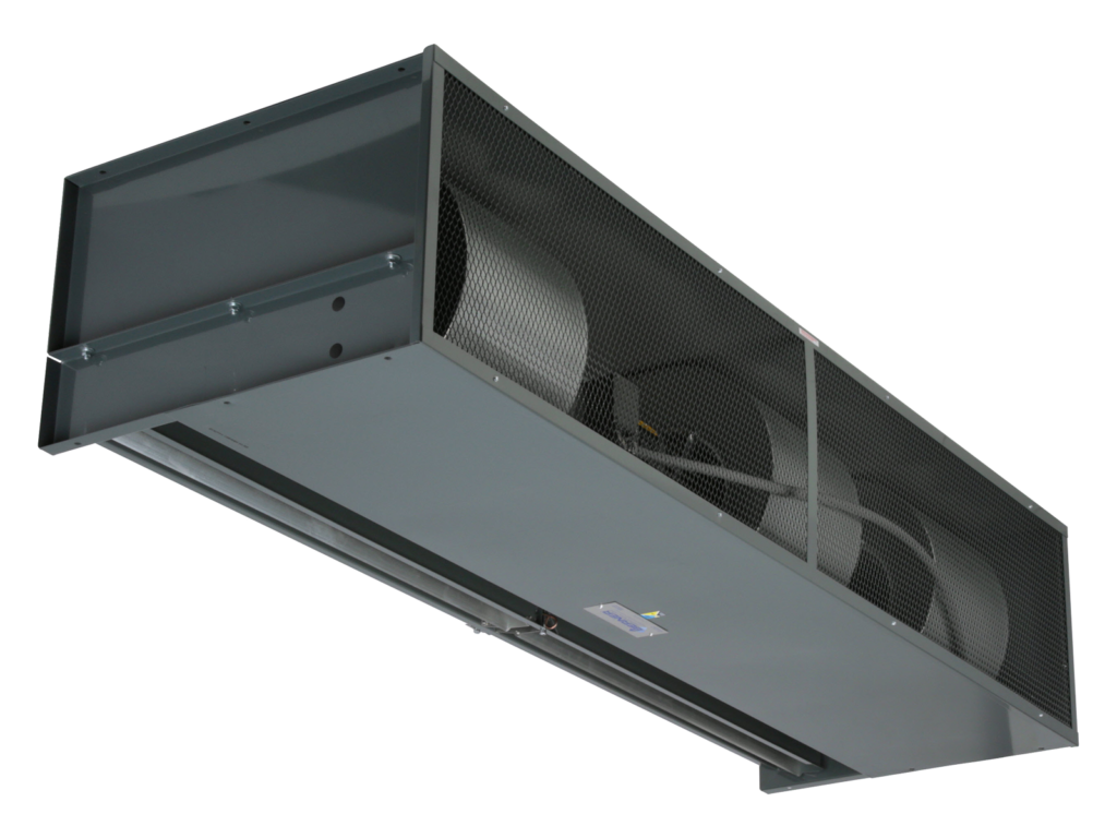
The Berner Hazardous Location Series 20 Air Curtain is designed and manufactured to comply with ANSI/NFPA-70 National Electrical Code (NEC) for Electrical Equipment: Class I, Division 1 and 2, Groups C and D for gases.
- Used in areas where gases may create a hazardous situation to keep temperatures stable and flying insects out when the doors are open.
- Engineered to perform and built to last
- Simple to install, operate, and maintain
- Made in U.S.A.
Available in single lengths from 5′ to 16′
AMBIENT
- Constructed for Class I, Division 1 & 2, Groups C & D
- 21″ high x 34″ deep
- Explosion-proof single-speed motor(s) temperature code T3C
- Interior and exterior gray zinc epoxy powder-coated aluminized steel cabinet with aluminized steel expanded metal screen
- Split cabinet construction for fan assembly removal
- External Mount Explosion Proof Junction Box (one per motor)
- Aluminum impellers in a matching housing
- Top and bottom mounting only
- High efficiency Pro-V Nozzle
STEAM/HOT WATER HEAT
- Constructed for Class I, Division 1 & 2, Groups C & D
- 21″ high x 34″ deep
- Explosion-proof single-speed motor(s) temperature code T3C
- Interior and exterior gray zinc epoxy powder-coated aluminized steel cabinet with aluminized steel expanded metal screen
- Split cabinet construction for fan assembly removal
- External Mount Explosion Proof Junction Box (one per motor)
- Aluminum impellers in a matching housing
- Top and bottom mounting only
- High efficiency Pro-V Nozzle
Coil features:
- Aluminum casing
- 5/8″ copper tube x .035″ wall
- Aluminum fins
- Leak tested at 450 psi
Accessories
This model requires an activation switch and a control panel.
CONTROL PANELS
Three-Phase Control Panels:
All three-phase power supplies require a three-phase control panel, remote (standard) or factory mounted, and an activation switch.
Standard Control Panel Construction:
Hazardous Location
- UL Classified NEMA 7 & 9 Aluminum Enclosure for Use in Class I, Division 1 & 2, Groups C & D Applications
- IEC Style Contactor, Solid State Adjustable Motor Overload(s), Control Transformer w/ Primary and Secondary Fusing (120V Control Voltage), Fusing (as required), Terminal Strip, and Time Delay or 24V Control (as required)
Standard Control Panel Construction:
Non-hazardous Location
- NEMA 4/12 Enclosure, Motor Contactor (factory wired), Motor Overload(s), 120 V Control Transformer, and Time Delay or 24 V Control (as required)
- Optional control panel enclosure constructions: poly fiberglass, aluminum, stainless steel
Control Panel Accessories
Hazardous Location
- Hand/off/automatic switches
- Start/stop push button(s)
- 24 V control
- Time delay
Non-Hazardous Location
- Disconnect switch(es) — toggle disconnects based on number of power supplies required
Electrical Accessories
Hazardous Location
- Door switches: side plunger style
- Hand/off/automatic switches
- Start/stop push button(s)
- Remote thermostat
Mechanical Accessories
- Wall support brackets
- 12″ extension brackets
- 2″ washable aluminum filters with frame

